GPIO & Real Boards
So far we have been running all our code using the feather-nrf52840-sense board.
In this tutorial, we will learn how to use the GPIO pins on a real board to control LEDs or read button presses.
For this tutorial I will be using a the feather-nrf52840-sense board with the Teamagochi PCB, but you can use any board that has GPIO pins.
Step 1: Configuring our Board
First, we need to actually inform RIOT about the board we are using.
To do this we need to change the BOARD variable in our Makefile to the board we are using.
BOARD ?= feather-nrf52840-sense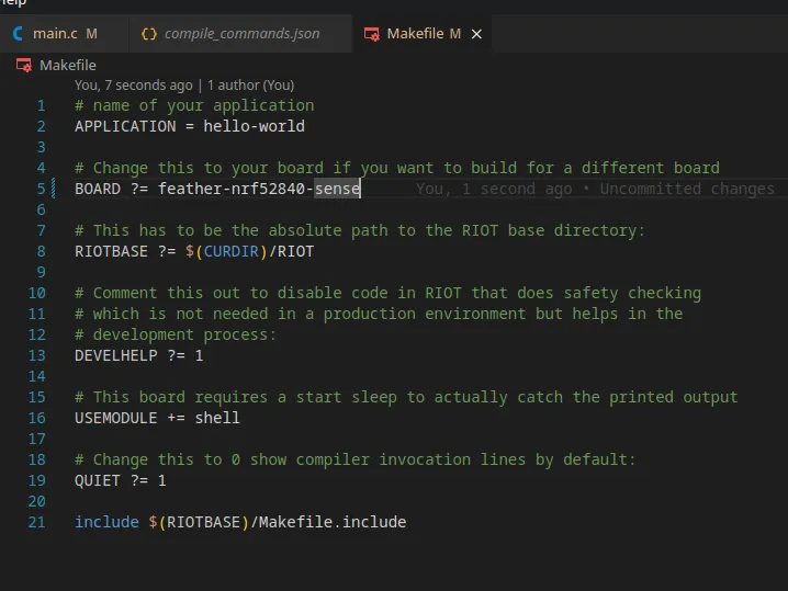
Try flashing the board with make flash and see if it works,
it should still execute the same code as before but now using the actual board.
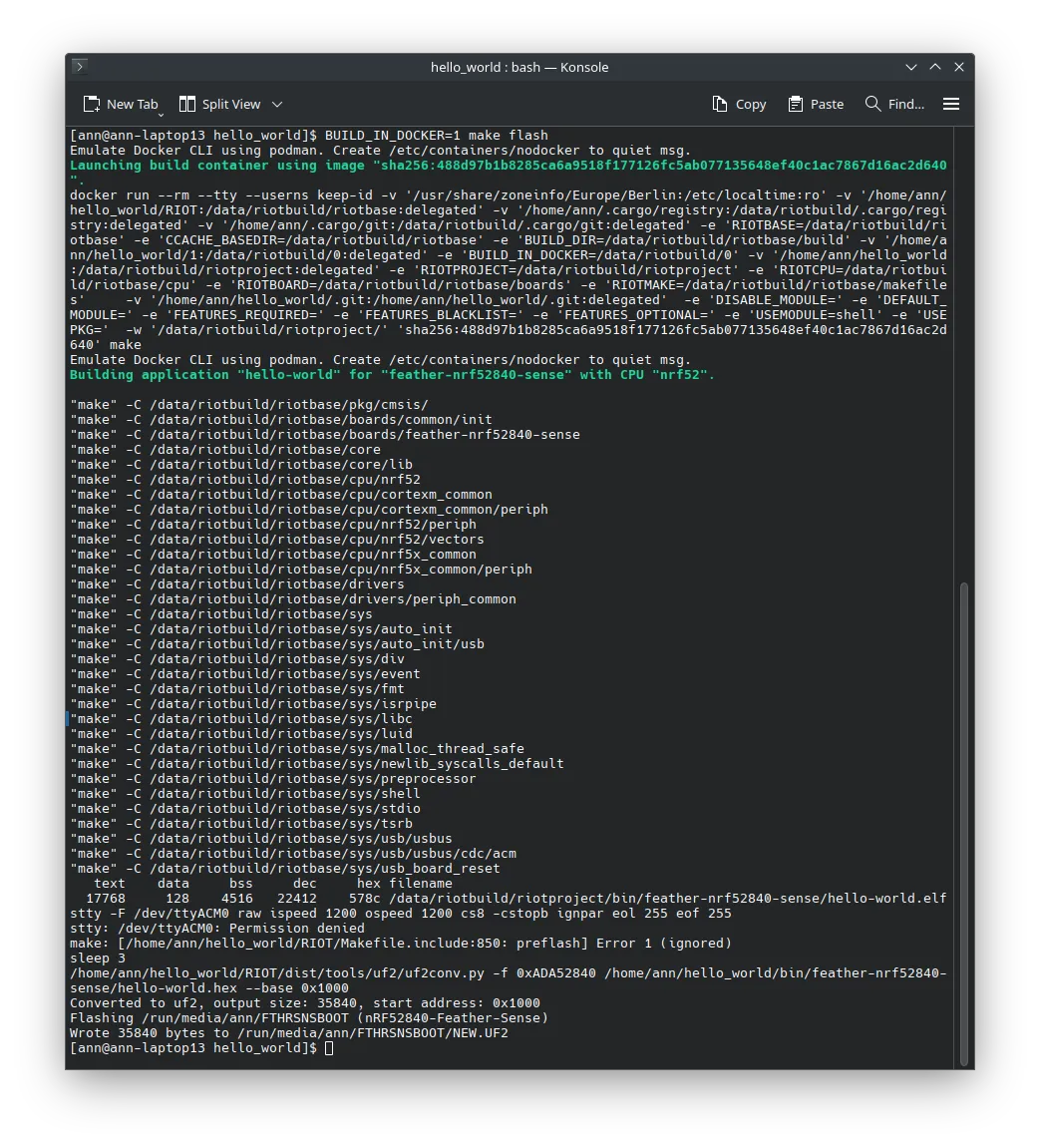
Now if we type make term we should see the output of the board in the terminal.
Make sure that you have the board connected to your computer via USB and
that your user has the necessary permissions to access the serial port.
Step 2: Controlling LEDs
Now that we have the board working, let’s try to control the LEDs on the board.
The exact pins that control the LEDs might vary depending on the board you are using,
but in the case of the feather-nrf52840-sense board, the LED would be connected
on Port 1 Pin 9.
First we need to include the necessary modules in our projects Makefile.
# Add the gpio module to the buildUSEMODULE += periph_gpioUSEMODULE += periph_gpio_irq
# Enable the milliseconds timer.USEMODULE += ztimerUSEMODULE += ztimer_msec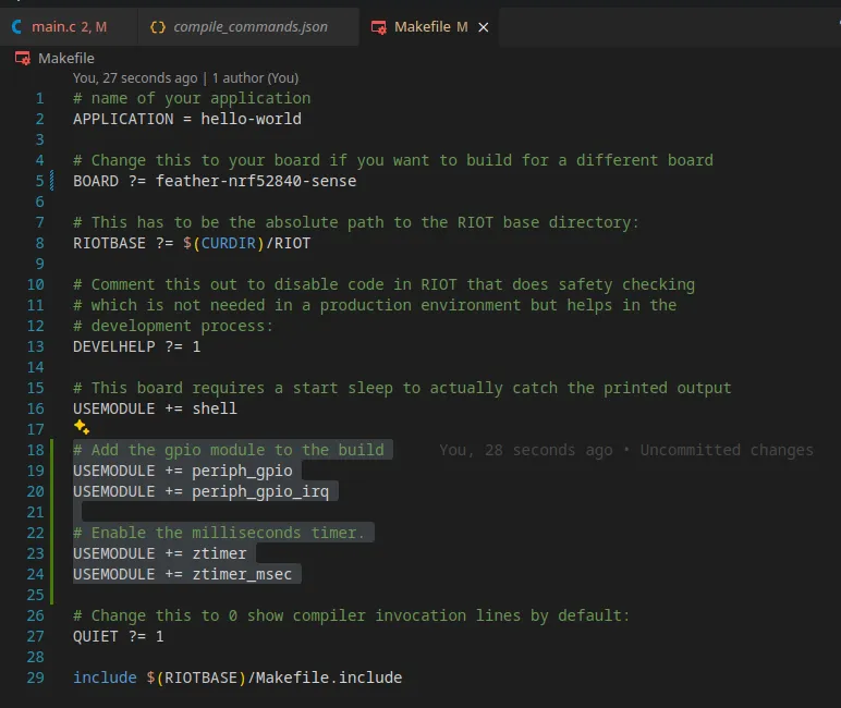
This allows us to both control the GPIO pins and timers.
Now we need to actually define the pin that we want to control in our code.
To do this include the following lines before the main function.
#include "periph/gpio.h"#include "board.h"#include "ztimer.h"
// Define the LED0 pin and modegpio_t led0 = GPIO_PIN(1, 9);gpio_mode_t led0_mode = GPIO_OUT;
Now we can control the LED by first initializing the pin and then clearing or setting it.
int main(void) {  // Initialize the LED0 pin  gpio_init(led0, led0_mode);  // Turn off the LED0 pin  gpio_clear(led0);
  while (1) {
  }}
This code will turn off the LED when the board starts which is quite boring, so let’s make it blink by adding a delay and toggling the LED.
while (1) { gpio_toggle(led0); ztimer_sleep(ZTIMER_MSEC, 500);}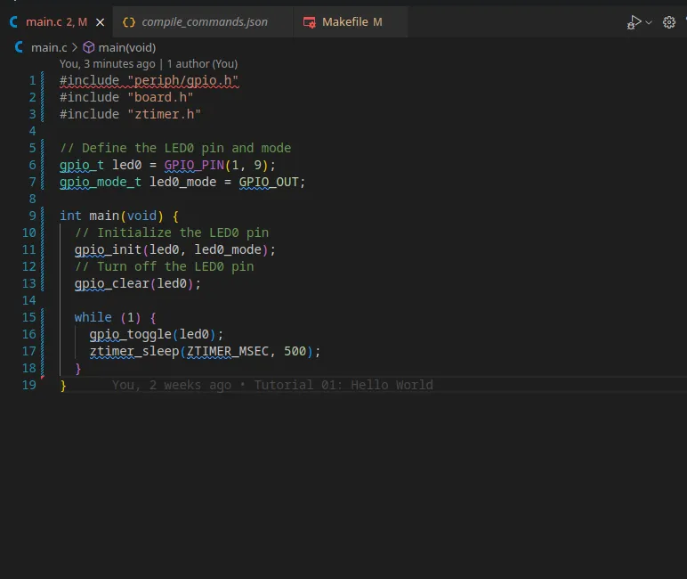
If we now make flash and then make term we should see the LED blinking.
Step 3: Reading Button Presses
If you remember what we did in the timers tutorial, we can use quite similar code to read button presses.
On a constrained device you usually don’t want to poll the button state, which is why we will use an interrupt to detect the button press, that way we can drastically reduce the power consumption of the device.
First we need to define the callback function that will be called when the button is pressed.
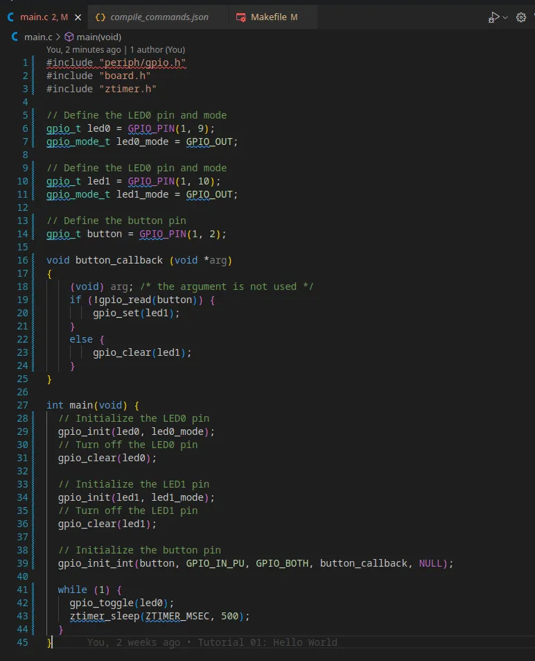
// Define the LED0 pin and modegpio_t led1 = GPIO_PIN(1, 10);gpio_mode_t led1_mode = GPIO_OUT;
void button_callback (void *arg){    (void) arg; /* the argument is not used */    if (!gpio_read(button)) {        gpio_set(led1);    }    else {        gpio_clear(led1);    }}
Now we need to define the button pin and mode and initialize it.
// Define the button pin and callbackgpio_t button = GPIO_PIN(1, 2);
int main(void) {    gpio_init_int(button, GPIO_IN_PU, GPIO_BOTH, button_callback, NULL);}
This code will initialize the button pin and call the button_callback function whenever the button is pressed.
If we now make flash and then make term we should see the LED turn on when the button is pressed.
Conclusion
In this tutorial we learned how to use the GPIO pins on a real board to control LEDs or read button presses.
This is a very basic example, but it should give you a good starting point to build more complex applications.